The following spacing tables are an alternative to the ICFWL spacing to replace anchor bolts tables or allowable loads. They give the spacing of the ICFWL Ledger Connectors based on the allowable vertical load of the connector, the load on the floor and the span of the joists. The designer must determine the design load, the ledger design and the joist design. This table is useful if the designer already has loads and spans, but not necessarily anchor bolt spacing.
*Values in the cells highlighted represent the maximum allowable spacing of 48".
-
Fasteners for wood ledgers provided with part
-
Loads apply to ICF foam thickness of 3 1/4" or less (For Thickness over 3 1/4 please contact us)
-
Concrete should have a minimum compressive rate of f'c = 2,500 psi (17.25 MPa)
-
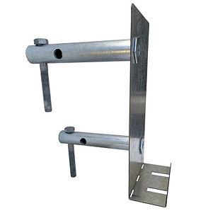
The bolts of a BURMON-ICFWL must be no closer than 4 inches to the top of wall.
-
*When attaching a deck to an ICF wall, place one 1/2" x 3 1/2" hex bolt into each cylinder bolt hole as shown
NOTE:
The Allowable Load Table is calculated in accordance with ASTM D7147-11 Section 13, the allowable downward load is calculated as the lesser of:
-
The lowest ultimate load per hanger divided by 3.
-
The average, over each hanger in each specimen, load that produces a vertical deflection of 0.125 inches at the bottom of the hanger with respect to the wall, Refer to Intertek Engineering report K9541.01-119-42 RO for test results.
5.* 1/2"x 3 1/2" Hex Bolt placement
-
Fasteners for steel ledgers provided with part #SLB
-
Minimum Steel ledger thickness is 16 gauge, 54mm steel ledger
-
Loads apply to ICF foam thickness of 3 1/4" or less.
-
Concrete should have a minimum compressive rate of f'c=2,500 psi (17.25 MPa)
-
The bolts of BURMON-ICFSL must be no closer than 4" to the top of wall
NOTE:
The Allowable Load Table is calculated in accordance with ASTM D7147-11 Section 13, the allowable downward load is calculated as the lesser of:
-
The lowest ultimate load per hanger divided by 3.
-
The average, over each hanger in each specimen, load that produces a vertical deflection of 0.125 inches at the bottom of the hanger with respect to the wall. Refer to Intertek Engineering report K9541.01-119-42 RO for test results.